CN


WeChat official account
The functions of each pin in the USB TYPE-C connector
Release time:2024-05-09Publisher:小编
Nowadays, embedded devices use a large number of different connectors, such as USB TYPE-B, MiniUSB, MICROUSB, etc. They differ in appearance, raincoats, and various other characteristics. In this case, the more appropriate solution is to minimize the number of connectors used and stop at one, which for most developers is' single '. It is more hopeful to use TYPE-C connectors. It combines incredible bandwidth and high power. Manufacturers such as Apple, Huawei, and Sony have introduced TYPE-C connectors into their designs, gradually abandoning the use of "old" connectors.
Why choose USB TYPE-C?
If you happen to not believe in the choices of developers for interfaces such as USB4, TUNDERBOLT 3 (TBT3), and ISPLAYPORT 2.0 (DP), which work through USB TYPE-C, then there are many descriptions of the various advantages of TYPE-C connectors for the Internet. We would like to present you with a small and useful "cheat sheet" that includes key features and practical application examples.
Here are the main features of TYPE-C connectors that you need to know.
Connector structure
TYPE-C provides many functions for each pin:
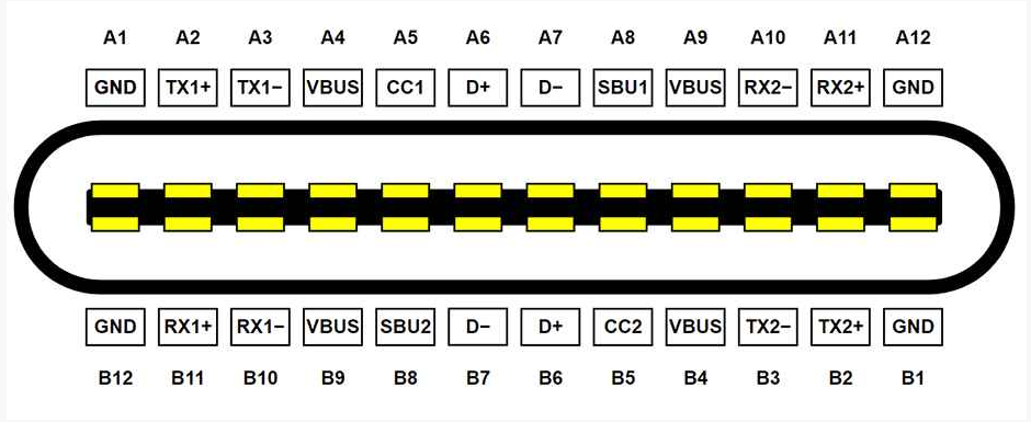
Consider their purpose:
VBUS - Power supply for equipment
Explanation: There are many different power transmission modes, ranging from 5V-500MA (2.5W) to 20V-5A (100W), but this makes it impractical and unsafe for the device to operate on a 20V power supply. The Power Supply (PD) protocol is used to negotiate voltages greater than 5V between devices and power sources. If this protocol is not available, the host device can provide a power of 15W (5V-3A). This is sufficient for almost any embedded device, but unfortunately, this power value (15W) depends on the configuration of the host device and is not always achievable.
Power Supply (PD) is a standard used to establish the roles between devices and the power levels between them.
Features:
Power without PD protocol -15W (U=5V, I=3A);
The power using PD protocol is 100W (U=20V, I=5A);
CC1/CC2- Configure Channel (CC)
Description: It is these pins that are responsible for determining the direction of the data line connection. In addition, depending on the direction of the data line connection, one of these pins becomes the power supply (VCONN) of the internal integrated circuit connected to the active data. The communication between devices using PD protocol occurs on the remaining second pin. For simple devices that do not require the use of PD protocol, the connection is determined passively: due to the formation of a resistive divider on the given line between the devices.
Features:
The power supply voltage on the VCONN line is -5V;
Current of VCONN line -200mA;
The signal level on the data line is 0-5V;
The frequency of signal variation on the data line is 400kHz (according to the PD protocol).
SBU1/SBU2 Sideband Usage (Auxiliary Signal Pin)
Explanation: These pins are optional for various interfaces. For interfaces such as USB2/3.2, these pins are not used. During the operation of the USB4 interface, these pins initialize the interface and additionally configure its operation, as well as initialize the data line and its direction. For DP interfaces, these pins perform the work of AUX channels. In audio adapter mode, one (depending on the connection direction) is used to simulate microphone signals, while the other is used to simulate ground.
features:
USB4- Serial Port with a speed of 1MBPS;
DISPLAYPORT - uses a data transfer rate of up to 720MBPS. It is a misconception to believe that audio is transmitted through this channel; In fact, audio data packets are transmitted together with video data packets through the main transmission channel (TX1 ± TX ± RX1 ± RX2 ±). The AUX channel is necessary for exchanging business information between devices, such as the initialization process on the line;
Audio adapter - uses analog signals ranging from -0.3V to 3.3V.
USB2/3.2- Not used;
D+/D Data (USB 2.0)
Description: A standard data cable with USB 2.0 interface. The signal repeats symmetrically on both sides of the connector to accommodate any direction of the data line. For other interfaces such as USB3.2/USB4/TBT3/DP, these pins are not used. So USB 2.0 can work in parallel with other interfaces. In audio adapter mode, these pins are used as the left and right channels for audio signals.
Features:
USB 2.0- data transfer with speeds up to 480MBPS;
Audio adapter - Use analog signal [-3.0 to 3.0V].
USB3.2/USB4/TBT3/DP - not used;
TX1 ± TX2 ± RX1 ± RX2 ± - Data (USB3.2/USB4/TBT3/DP)
Explanation: High frequency differential pairs required for data transmission. The baud rate varies for different interfaces. For USB4/TBT3/DP interfaces, all lines can be configured for one-way data transmission (simplex mode). Therefore, the data transmission rate doubles.
Features:
USB3.2 GEN1/GEN2- only uses two of the four channels (TX1/RX1 or TX2/RX2), depending on the direction of the connector. The data rate on each line is 5GBS (GEN1) and 10GBPS (GEN2);
USB 3.2 GEN 2X2- uses all four differential pairs (TX1/RX1 and TX2/RX2)
USB4/TBT3/DP - uses all four differential pairs (TX1/RX1 and TX2/RX2). The data transmission rate on each line is 20Gbps. Therefore, in duplex and simplex modes, the total transmission speed is 40GB/S (bidirectional) and 80GB/S, respectively.
 Dongguan Dongdu Electronics Co., Ltd
 0769 8286 1181
 188 1951 2262 (Mr. Zhang) / 136 9420 3733 (Mr. Luo)
 sale@dongdudz.com
 Building A, No. 46 Huayuan New Street, Tangxia Community, Tangxia Town, Dongguan City